ELEMENTS OF TRANSMISSION AND RECEIVER
1. Radio equipment
A radio set consists essentially of: a transmitter that generates radio frequency (RF) energy; a source of electrical power a key, microphone, or teletypewriter, that controls these energy waves; a transmitting antenna that radiates RF waves; a receiving antenna that intercepts some of the radiated RF waves; a source of electrical power; a receiver that converts intercepted RF waves into usable energy (usually audio frequency (AF) energy); and a loudspeaker, headphones, or teletypewriter provided intelligibility.
When the frequency coverage of two sets is similar, when they have the same modulation, and the distance between them does not exceed the range of the equipment, two-way communications using electromagnetic (radio) waves is possible. Figure 1 is a block diagram of a basic radio set.
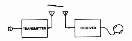
Figure 1. Block Diagram of Basic Radio Set.
2. Radio transmitter
The simplest radio transmitter (figure 2) consists of a power supply and an oscillator. The power supply can be batteries, a generator, an alternating-current (AC) power source, including a rectifier and filter or a direct-current (DC) rotating power source. The oscillator, which generates RF alternating current, must contain a tuned circuit to tune the transmitter to the desired operating frequency.
The transmitter must also have some device for controlling the generated RF energy. The simplest device is a telegraph key, which is merely a type of switch for controlling the flow of electric current. When the key is operated, the oscillator is turned on and off for varying lengths of time to form dots and dashes of RF energy. Figure 2. Block Diagram of a Simple Radio Transmitter.
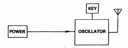
Figure 2. Block Diagram of a Simple Radio Transmitter.
3. Antennas
After an RF signal has been generated and amplified in the transmitter, a means must be provided to radiate this RF energy into space. At the same time, a means must be provided at the receiver location to intercept (pick up) the signal. The device that fulfills these requirements is called an antenna.
The transmitting antenna sends transmitter signal energy out into space. This energy, radiated in the form of electro-magnetic waves, is intercepted by a receiving antenna. If the receiver is tuned to the same frequency as the transmitter, the signal will be received and intelligible information made available.
4. Radio receiver
4.1 Detector (demodulator)
There are two general kinds of RF signals that can be received by a radio receiver: modulated RF signals that carry speech, music, or other audio energy, and continuous wave (CW) signals that are a burst of RF energy conveying intelligence by means of code (dot) signals. The process whereby the intelligence carried by an RF signal is extracted is called detection or demodulation.
The circuit used to accomplish this is called a detector (figure 3), since it actually detects the incoming intelligence. The receiver must have some means of tuning in or selecting the frequency of the desired RF signal. This selective action is necessary to avoid the detection of many RF signals or different frequencies at the same time. That part of the detector which is used to tune in the desired signal is called a tuned circuit. In FM radio receivers, the detector is known as a discriminator.
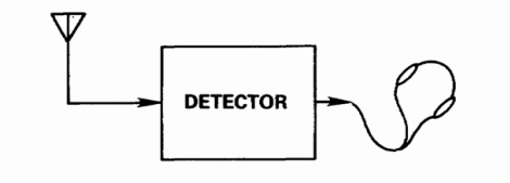
Figure 3. Block Diagram of Simple Radio Receiver.
4.2 RF amplifier
Because an RF signal diminishes in strength or amplitude at a very rapid rate after it leaves the transmitting antenna and because many RF signals of various frequencies are crowded into the radio frequency spectrum, a detector is not used alone.
An RF amplifier (figure 4) is included in the receiver to increase the sensitivity (ability to receive weak signals) and the selectivity (ability to separate signals of different radio frequencies). The RF amplifier is provided with one or more tuned circuits so that the desired RF signal (the one to which it is tuned) is amplified more than RF signals of other frequencies.
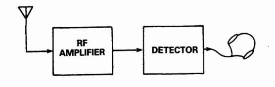
Figure 4. Block Diagram of Detector and RF Amplifier.
4.3 Audio frequency amplifier
The power output of a detector, with or without an RF amplifier, is generally too little to be useful. One or more audio frequency amplifiers (figure 5), therefore, are added to the receiver to increase the audio frequency power to a level that will operate headphones, a loudspeaker, or teletypewriter equipment.
The power output of a detector, with or without an RF amplifier, is generally too little to be useful. One or more audio frequency amplifiers (figure 5), therefore, are added to the receiver to increase the audio frequency power to a level that will operate headphones, a loudspeaker, or teletypewriter equipment.
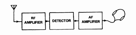
Figure 5. Block Diagram of Complete Radio Receiver
Now you have an understanding of these areas, please go to the podcast to listen to an explanation of receiver.
If you want see the explin of this lecture in video plaese watch this video
